

Error of axial disassembly of diaphragm coupling
The core component of the diaphragm coupling can be divided into beam waist type, ring type, combined link type, spokes and multiple modes according to the shape of the diaphragm.According to the working condition of the coupling, we can summarize the force of the coupling into the following four types, and give the planning method of different types of force, taking the eight-hole waist diaphragm as the research about the image.
(1) Bending stress caused by angular disassembly error.It can be solved according to the simplification of the figure below.Due to the theoretical error of disassembly in the axial angular direction, the diaphragm is periodically bent and deformed along the axial position. Moreover, it is the main reason that determines the fatigue of the coupling diaphragm.According to the displacement of the bolt hole in the axial position, radial displacement and axial displacement caused by the reason of the angular direction.The measurement of the restoring moment H can be obtained by the angle inclination. Generally, the angular displacement of the coupling diaphragm is very small, so the diaphragm deformation is a small deformation, which can be analyzed by the small deflection bending theory of the thin plate.
(2) Due to the error of axial disassembly, the diaphragm is bent and deformed along the axis.The displacement loads the position of the axis at the local bolt hole, and the radial displacement and axial displacement are active.The space between the two ends at both ends is used to impose a restraint, and a hole is placed to bear the load.In this way, treat it as a statically determinate simply supported mechanism.
(3) Centrifugal stress due to inertia during high-speed spinning.Assuming bolts and
Coupling diaphragm
With the same material, the respective masses can be planned. According to the position and the spiral angle, the centrifugal force can be calculated, and it acts on the total center of mass.The centrifugal inertia force of high-speed equipment is extremely important in the customized stress plan. The centrifugal inertia force can be loaded according to the radial force F=(2n/60)2rp, and the position is radially outward, and the radial displacement of the bolt hole in the movable place , Circumferential displacement and axial displacement, no other loads around.
(4) Film stress caused by torque production.Suppose the transmitted torque is T(Nm), and the total number of pieces is m. For 8-hole bolts, the simplified conditions know: the torque of a single diaphragm is T1=T/m, and the force on each main bolt is F=T/4mR.
relevant information
- Function of coupling
- Treatment method and lubrication of gear coupling failure
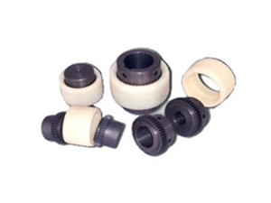
- The reason why plum coupling is often damaged
- The difference between star coupling and plum coupling
- The structure and advantages of JQ type clamp coupling
- How to install and connect the coupling
- Installation technology of drum gear coupling
- The keyway type and code of the shaft hole of the diaphragm coupling
Ranking of similar articles
- Function of coupling
- Treatment method and lubrication of gear coupling failure
- The reason why plum coupling is often damaged
- The difference between star coupling and plum coupling
- The structure and advantages of JQ type clamp coupling
- How to install and connect the coupling
- Installation technology of drum gear coupling
- The keyway type and code of the shaft hole of the diaphragm coupling
- Specifications and parameters of plum coupling
- Advantages of elastic pin coupling